1. Background

The São Paulo Museum of Art (MASP) building is built using four concrete columns supporting four prestressed concrete beams that support both floors of the gallery. The structural analysis and construction process can be found from the paper “Construction of the museu de arte de são paulo” by Gabriela Campagnol and Stephen Caffey and member dimensions can be found from the document “MASP’s Structure Conservation Plan”. This project focuses on redesigning the columns with two objectives, minimizing material usage and optimizing for mechanical strength.
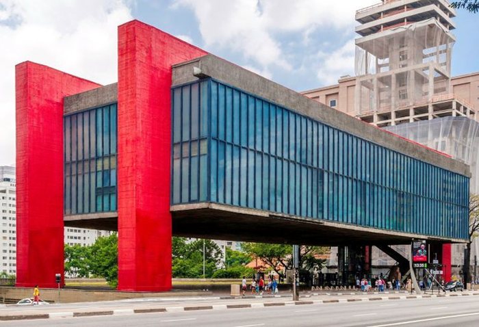
Figure 1: MASP building street view
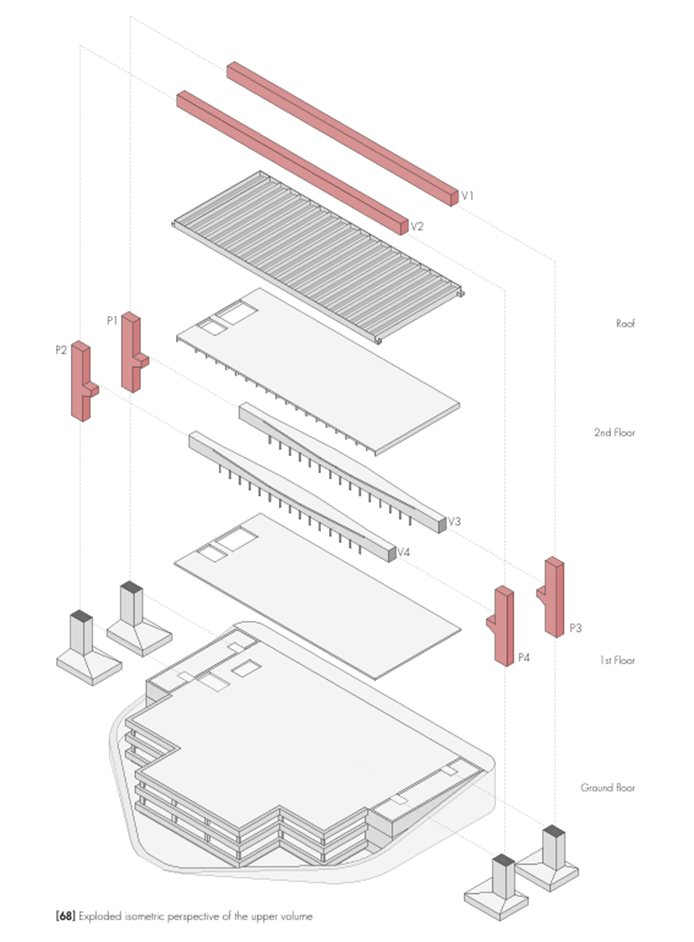
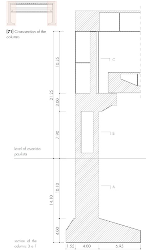
The design domain for the proposed columns is modeled based on these dimensions. For this analysis, I am only considering the volume above the foundation. The shaded part of the column represents structural concrete, with the lower half of the section being hollow and the top half being filled in with non structural concrete. The two beams acting on the column will represent loads with the top of the foundation acting as a fixed support.

Figure 2: Masp 3D exploded layout

Figure 3: Column dimensions

2. Boundary Conditions

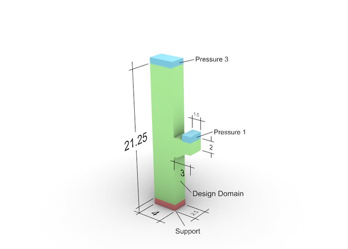
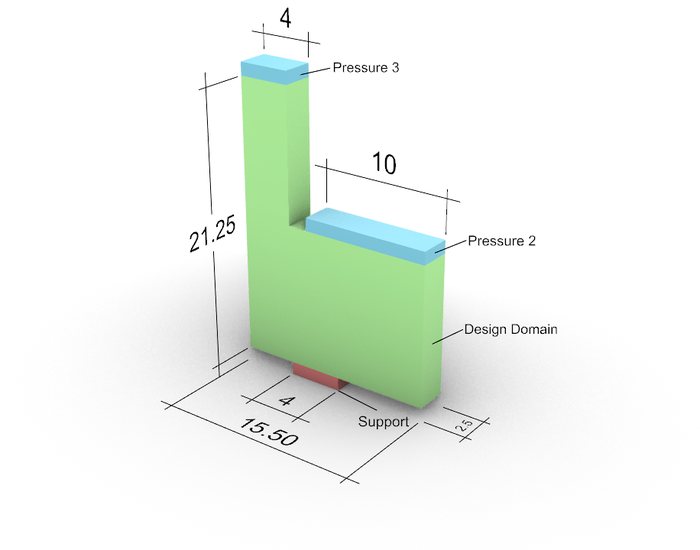
Two boundary conditions are chosen. One is made from volume, loading, and supports used from the original column. The second boundary condition is made to better support the lower beam by extending the console support area from 3.75 m2 to 25 m2 while expanding the volume to cover all space below as well.

Figure 4: Boundary condition 1

Using the beam dimensions, cross sectional areas, and assuming normal density concrete (24kN/m3):

- Roof beam: 5672.16 kN

- Floor beam: 7509.6 kN

- Pressure 1: (7509.6 / 2)/ 3.75 = 1001.28 kN/m2

- Pressure 2: (7509.6 / 2)/ 25 = 150.2 kN/m2

- Pressure 3: (5672.16 / 2) / 10 = 283.6 kN/m2

3. Optimization

Figure 5: Boundary condition 2
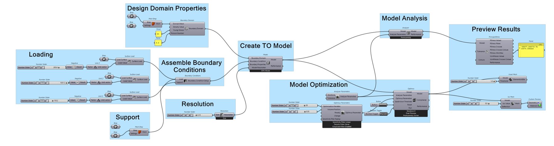
Figure 6: Topos script in Grasshopper
Table 1: Parameters used
Young ModulusPoisson NumberResolutionIterationsVolume FractionPenaltyChangeSensitivity Radius
50 GPa0.20.1300.3520.051.5

The four main columns will be redesigned using a SIMP based approach using the Topos plugin in Grasshopper. Topos is a 3D topology optimization plugin which uses the GPU for computational acceleration and is based on CUDA technology provided by NVIDIA, meaning a NVIDIA graphics card is needed to run the plugin. Since Topos uses the SIMP based approach, the objective function is to minimize structural compliance subject to the volume constraint and the design variables.

4. Results

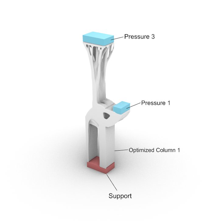
Figure 7 shows the optimized column design given the domain of the column featured in the MASP building. Since pressure 1 is so much larger than pressure 3, the majority of the stresses and material were focused around the console rather than the roof. Furthermore, it can be seen why a lower hollow cross section segment and thin upper segment were used for the original column as the results show that material is not actually necessary for those regions.

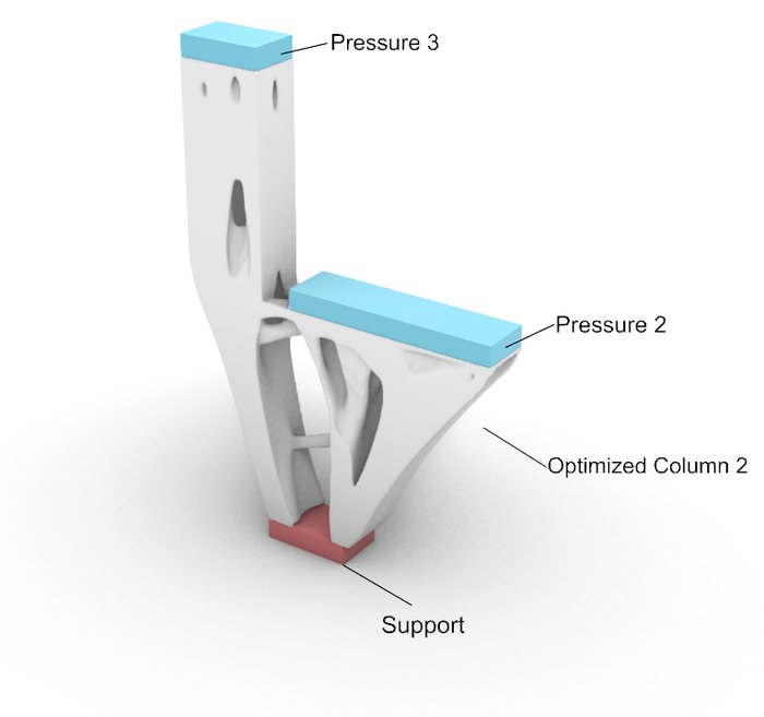
Figure 8: Optimized column 2

Figure 7: Optimized column 1

Figure 8 shows the optimized design domain given boundary conditions 2 which were meant to highlight a design alternative where the console length is extended from 1.5 meters to 10 meters allowing for the pressures to be more balanced, which is why there is a visually equal amount of material assigned to both regions.

Table 2: Topology optimization results
Volume (m3)Max Compressive Stress (MPa)Max Tensile Stress (MPa)
Initial Column210.31127.21270.18
Optimized Column 192.31127.21270.18
Optimized Column 2197.3134.90115.34

Column 1, as seen in figure 7, has a volume that is 56% lower than the original column,while maintaining the same compressive and tensile stresses as the original column. While column 2, as seen in figure 8, has a volume 6.2% lower with a 72.6% and a 57.3% decrease in maximum compressive and tensile stresses respectively. For industry applications the optimal selection of which solution to pick depends on what the objective of the optimization is. If the goal is to reduce material usage as much as possible, then column 1 is good. If the goal is to create a more strengthened structure then column 2 is preferable.

5. Renders and Fabrication

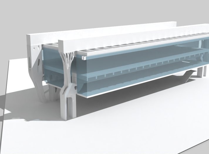
Figure 9: MASP aerial render

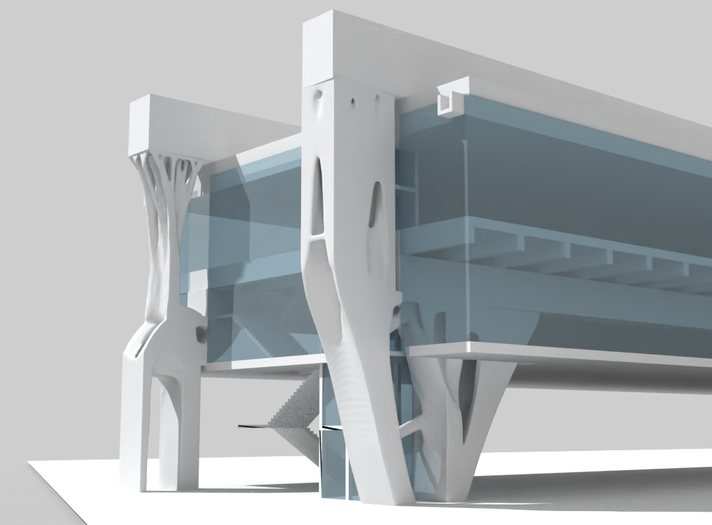
Figure 10: MASP street render

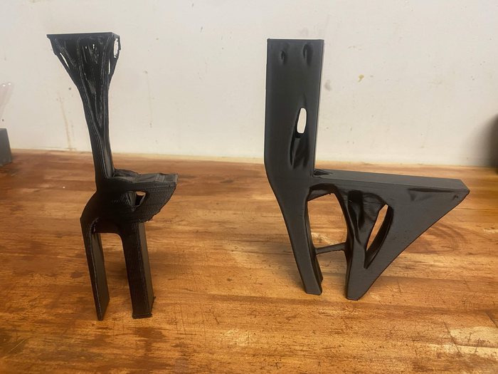
Figure 11: 3D printed columns